[PA-03c] Read temperature DHT21 with Qt

Another useful code from Vannevar Morgan, you can check these out:
youtube: https://www.youtube.com/watch?v=1PNn63P793Y

github: https://github.com/vannevar-morgan/Qt-Temperature-Sensor

However, I do not use the temperature DS18B20. I use temperature and humidity DHT21. And in Qt code, I use Celcius degree instead of Fahrenheit degree. In Arduino code, I use header file floatToString to display the data to LCD.

 pyqt_dht.ino


/*
 * Date: Wed, 10/05/2017
 * Desc: Read Temperature and Humidity from DHT21
 * Display on LCD
 * Send to PC via serial
 */
#include <Wire.h>
#include <LCD.h>
#include <LiquidCrystal_I2C.h>
#include "DHT.h"
#include "floatToString.h"

#define I2C_ADDR 0x3F 
#define BACKLIGHT_PIN 3
#define En_pin 2
#define Rw_pin 1
#define Rs_pin 0
#define D4_pin 4
#define D5_pin 5
#define D6_pin 6
#define D7_pin 7
LiquidCrystal_I2C lcd(I2C_ADDR,En_pin,Rw_pin,Rs_pin,D4_pin,D5_pin,D6_pin,D7_pin);

#define DHTPIN 9
#define DHTTYPE DHT21
DHT dht(DHTPIN, DHTTYPE);
float t;
float h;
char bufferstore[20]; // used by floatToString to display on LCD

void setup() {
 delay(1000);
 // Initialize Serial
 Serial.begin(9600); 
 // Initialize DHT
 dht.begin();

// Initialize LCD
 lcd.begin(16,2);
 lcd.setBacklightPin(BACKLIGHT_PIN,POSITIVE);
 lcd.setBacklight(HIGH); 
}

void loop() {
 // Read sensor parameter
 h = dht.readHumidity();
 t = dht.readTemperature();
 // Display on LCD
 lcd_display_temp_humid(t,h);
 // Send via serialport
 Serial.print(t);
 Serial.print(",");
 Serial.flush();
 // Delay for next round
 delay(2000);
}

void lcd_display_temp_humid(float temperature, float humidity){
 lcd.clear();
 lcd.print("Tempe: ");
 lcd.print(floatToString(bufferstore, temperature, 2, 5, true));
 lcd.print(" C");
 lcd.setCursor(0,1);
 lcd.print("Humid: ");
 lcd.print(floatToString(bufferstore, humidity, 2, 5, true));
 lcd.print(" %");
}

floatToString.h


// floatToString.h
//
// Tim Hirzel
// tim@growdown.com
// March 2008
// float to string
// 
// If you don't save this as a .h, you will want to remove the default arguments 
// uncomment this first line, and swap it for the next. I don't think keyword arguments compile in .pde files

//char * floatToString(char * outstr, float value, int places, int minwidth=, bool rightjustify) {
char * floatToString(char * outstr, float value, int places, int minwidth=0, bool rightjustify=false) {
 // this is used to write a float value to string, outstr. oustr is also the return value.
 int digit;
 float tens = 0.1;
 int tenscount = 0;
 int i;
 float tempfloat = value;
 int c = 0;
 int charcount = 1;
 int extra = 0;
 // make sure we round properly. this could use pow from <math.h>, but doesn't seem worth the import
 // if this rounding step isn't here, the value 54.321 prints as 54.3209

// calculate rounding term d: 0.5/pow(10,places) 
 float d = 0.5;
 if (value < 0)
 d *= -1.0;
 // divide by ten for each decimal place
 for (i = 0; i < places; i++)
 d/= 10.0; 
 // this small addition, combined with truncation will round our values properly 
 tempfloat += d;

// first get value tens to be the large power of ten less than value 
 if (value < 0)
 tempfloat *= -1.0;
 while ((tens * 10.0) <= tempfloat) {
 tens *= 10.0;
 tenscount += 1;
 }

if (tenscount > 0)
 charcount += tenscount;
 else
 charcount += 1;

if (value < 0)
 charcount += 1;
 charcount += 1 + places;

minwidth += 1; // both count the null final character
 if (minwidth > charcount){ 
 extra = minwidth - charcount;
 charcount = minwidth;
 }

if (extra > 0 and rightjustify) {
 for (int i = 0; i< extra; i++) {
 outstr[c++] = ' ';
 }
 }

// write out the negative if needed
 if (value < 0)
 outstr[c++] = '-';

if (tenscount == 0) 
 outstr[c++] = '0';

for (i=0; i< tenscount; i++) {
 digit = (int) (tempfloat/tens);
 itoa(digit, &outstr[c++], 10);
 tempfloat = tempfloat - ((float)digit * tens);
 tens /= 10.0;
 }

// if no places after decimal, stop now and return

// otherwise, write the point and continue on
 if (places > 0)
 outstr[c++] = '.';


 // now write out each decimal place by shifting digits one by one into the ones place and writing the truncated value
 for (i = 0; i < places; i++) {
 tempfloat *= 10.0; 
 digit = (int) tempfloat;
 itoa(digit, &outstr[c++], 10);
 // once written, subtract off that digit
 tempfloat = tempfloat - (float) digit; 
 }
 if (extra > 0 and not rightjustify) {
 for (int i = 0; i< extra; i++) {
 outstr[c++] = ' ';
 }
 }


 outstr[c++] = '\0';
 return outstr;
}

Till now, I am just a copier without clearly understand how things are done. I have temperature and humidity but only show one of them. The main loop of Arduino has to send the data continuously. It is not practical. The right procedure is when PC sends command to Arduino, Arduino responses. I hope to do better job next time.

PS: remember 10k pick-up resistor of DHT signal pin.

[PA-03b] Control RGB Led with slider Qt

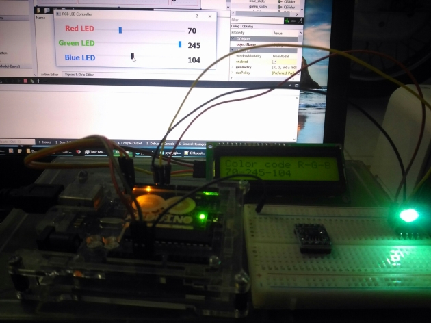
I used the code of Mr.Vannevar Morgan and modified Arduino code in order to display RGB value on LCD I2C. Please check this link to see his youtube tutorial and github code
youtube: https://www.youtube.com/watch?v=5uuFlSzzYsc

github: https://github.com/vannevar-morgan/Qt-RGB-LED

The idea is similiar with the [PA-03a], you send command to Arduino and Arduino does correspondingly. Since we have 3 values of R-G-B so to discriminate them, we have to add prefix ‘r’ for Red, ‘g’ for Green and ‘b’ for Blue before brightness value. Here is my Arduino code:


/*
 * Date: Tue, 09/05/2017
 * Desc: Receive command from python to adjust RGB color
 * Convert message into integer, PWM on pin 9, 10, 11
 * Give feedback message syntax (R,G,B) displayed on LCD
 */
#include <Wire.h>
#include <LCD.h>
#include <LiquidCrystal_I2C.h>

#define I2C_ADDR 0x3F 
#define BACKLIGHT_PIN 3
#define En_pin 2
#define Rw_pin 1
#define Rs_pin 0
#define D4_pin 4
#define D5_pin 5
#define D6_pin 6
#define D7_pin 7
LiquidCrystal_I2C lcd(I2C_ADDR,En_pin,Rw_pin,Rs_pin,D4_pin,D5_pin,D6_pin,D7_pin);

#define red_led 9
#define green_led 10
#define blue_led 11
int rgb_val[3];

void setup()
{
 delay(1000);
 // Initialize pinMode
 pinMode(red_led, OUTPUT);
 pinMode(green_led, OUTPUT);
 pinMode(blue_led, OUTPUT);
 setPwmFrequency(red_led, 8); //Set pin 9's PWM frequency to 3906 Hz (31250/8 = 3906)
 setPwmFrequency(green_led, 8);
 setPwmFrequency(blue_led, 8);
 rgb_val[0] = 0; // This is the only way
 rgb_val[1] = 100;
 rgb_val[2] = 0;
 analogWrite(red_led, rgb_val[0]);
 analogWrite(green_led, rgb_val[1]);
 analogWrite(blue_led, rgb_val[2]);

// Initial LCD
 lcd.begin(16,2);
 lcd.setBacklightPin(BACKLIGHT_PIN,POSITIVE);
 lcd.setBacklight(HIGH);
 lcd_display_command(rgb_val);
 lcd.setCursor(0,0);
 lcd.print("Initial R-G-B ");
 
 // Initialize serial
 Serial.begin(9600);
}

void loop()
{
 if (Serial.available()){
 char led_specifier = Serial.read();
 int led_brightness = Serial.parseInt();
 write_leds(led_specifier, led_brightness);
 }
}

void write_leds(char led, int brightness)
{
 if (led == 'r'){
 analogWrite(red_led, brightness);
 rgb_val[0] = brightness;
 lcd_display_command(rgb_val);
 return;
 }
 if (led == 'g'){
 analogWrite(green_led, brightness);
 rgb_val[1] = brightness;
 lcd_display_command(rgb_val);
 return;
 }
 if (led == 'b'){
 analogWrite(blue_led, brightness);
 rgb_val[2] = brightness;
 lcd_display_command(rgb_val);
 return;
 } 
 return;
}

// change the frequency of PWM
void setPwmFrequency(int pin, int divisor) {
 byte mode;
 if(pin == 5 || pin == 6 || pin == 9 || pin == 10) {
 switch(divisor) {
 case 1: mode = 0x01; break;
 case 8: mode = 0x02; break;
 case 64: mode = 0x03; break;
 case 256: mode = 0x04; break;
 case 1024: mode = 0x05; break;
 default: return;
 }
 if(pin == 5 || pin == 6) {
 TCCR0B = TCCR0B & 0b11111000 | mode;
 } else {
 TCCR1B = TCCR1B & 0b11111000 | mode;
 }
 } else if(pin == 3 || pin == 11) {
 switch(divisor) {
 case 1: mode = 0x01; break;
 case 8: mode = 0x02; break;
 case 32: mode = 0x03; break;
 case 64: mode = 0x04; break;
 case 128: mode = 0x05; break;
 case 256: mode = 0x06; break;
 case 1024: mode = 0x07; break;
 default: return;
 }
 TCCR2B = TCCR2B & 0b11111000 | mode;
 }
}
// display on LCD 16x2
void lcd_display_command(int rgb_value[3]){
 lcd.clear();
 lcd.print("Color code R-G-B");
 lcd.setCursor(0,1);
 String content = String(rgb_value[0]) + "-" + String(rgb_value[1]) + "-" + String(rgb_value[2]);
 lcd.print(content);
}

There are some need-improve things. First, at the initializing state, if you are not happy with my R-G-B value = [0, 100, 0] and you want to change this, you have to change the initial value of the slider. So you need code to update the initial state at the beginning of Qt.

Second, the LCD seems to fade when you are dragging the slider (if you click, LCD displays quickly) so I think there is some uncertainty when you deal with the function slider_value_change. I will follow up this tutorial (maybe feedback message with time logging, yeah that is good, yay me)

Third, only one channel value (Red, Green or Blue) is sent at a time. It is not practical in the real life because you have to send a data block of 3 values. For example you have a color pallet and you pick a point on the pallet, the RGB value will change all of 3 value. I am thinking about sending a number (with binary from for enhancing transfer speed)


(256^2)*R + (256^1)*G + (256^0)*B


and a prefix (like modbus: one byte address, one byte value). So this tutorial will be suspended for further improvement.

[PA-03a] Create GUI with Qt

In this tutorial, we focus on building a GUI that gives command to Arduino and Arduino will display the received command, turn Led on-off and give feedback message. The main content will how to use Qt to make GUI. Easy thing on first, here is the code of Arduino
pyqt_blink_feedback.ino


/*
 * Date: Fri, 05/05/2017
 * Desc: Blink Led 13 when receiving command
 * and give feedback message
 * also display lcd i2c command
 */
#include <Wire.h>
#include <LCD.h>
#include <LiquidCrystal_I2C.h>

#define I2C_ADDR 0x3F 
#define BACKLIGHT_PIN 3
#define En_pin 2
#define Rw_pin 1
#define Rs_pin 0
#define D4_pin 4
#define D5_pin 5
#define D6_pin 6
#define D7_pin 7
LiquidCrystal_I2C lcd(I2C_ADDR,En_pin,Rw_pin,Rs_pin,D4_pin,D5_pin,D6_pin,D7_pin);

// Used for pin status
int ledPin = 13;

// Used for serial 
char incomingChar;

void setup() {
 // Initial process
 delay(1000);
 pinMode(ledPin, OUTPUT); // declare LED as output
 digitalWrite(ledPin, LOW);
 Serial.begin(9600);
 Serial.println("Ready for command.");

lcd.begin(16,2);
 lcd.setBacklightPin(BACKLIGHT_PIN,POSITIVE);
 lcd.setBacklight(HIGH);
 lcd.clear();
 lcd.print("Waiting command:");
}

void loop(){
 // when characters arrive over the serial port...
 if (Serial.available()){
 // wait a bit for the entire message to arrive
 delay(100);
 while (Serial.available() > 0) {
 incomingChar = Serial.read();
 lcd_display_command(String(incomingChar));
 if (incomingChar == '1'){ 
 digitalWrite(ledPin, HIGH);
 Serial.println("Led is turn on."); 
 } else if (incomingChar == '0'){
 digitalWrite(ledPin, LOW);
 Serial.println("Led is turn off."); 
 } else {
 Serial.println("Error.");
 }
 // Post processing, clear incomingChar
 incomingChar = ' ';
 }
 }
}

void lcd_display_command(String content){
 lcd.clear();
 lcd.print("Received command");
 lcd.setCursor(0,1);
 lcd.print(content);
}

Step 1: download PyQt 4.10 x32 at SourceForge URL: https://sourceforge.net/projects/pyqt/files/PyQt4/PyQt-4.10/PyQt4-4.10-gpl-Py2.7-Qt4.8.4-x32.exe/download and install to your computer

Step 2: create folder pyqt_blink_command

Open Qt designer, New Form will show up --> pick Dialog without Button --> Create.

Step 2.1: modify the windowTitle of Dialog into Control Led with feedback

Step 2.2: create Text Browser --> Drag and Drop TextBrowser (Display Widget) to Dialog

Step 2.3: create Button --> Drag and Drop PushButton to Dialog --> change Text to Turn on (because initially Led 13 is off)

Step 2.4: save form with name ArduinoLed.ui in folder pyqt_blink_command

Step 3: cmd --> change directory to folder pyqt_blink_command --> convert file .ui to file .py


pyuic4 -x ArduinoLed.ui -o ArduinoLedUI.py

Right click on ArduinoLedUI.py --> Edit with IDLE. We can Run this code for testing first.

Step 4: modify code that is converted from .ui, including: import serial library, write function for button and display the feedback message

Step 4.1: import the serial library at the beginning of the code

[modified ArduinoLedUI.py]


# -*- coding: utf-8 -*-

# Form implementation generated from reading ui file 'ArduinoLed.ui'
#
# Created: Fri May 05 14:43:31 2017
# by: PyQt4 UI code generator 4.10
#
# WARNING! All changes made in this file will be lost!

import sys, time, serial
from PyQt4 import QtCore, QtGui

try:
 _fromUtf8 = QtCore.QString.fromUtf8
except AttributeError:
 def _fromUtf8(s):
 return s

try:
 _encoding = QtGui.QApplication.UnicodeUTF8
 def _translate(context, text, disambig):
 return QtGui.QApplication.translate(context, text, disambig, _encoding)
except AttributeError:
 def _translate(context, text, disambig):
 return QtGui.QApplication.translate(context, text, disambig)

class Ui_Dialog(object):
 def setupUi(self, Dialog):
 # declaration for serial port and initialize variable
 self.LedStatus = 0 # Led status showing on-off
 self.arduino = serial.Serial('COM3', 9600)
 txtArduino = self.arduino.readline()
 txt = "Arduino> " + txtArduino
 #
 Dialog.setObjectName(_fromUtf8("Dialog"))
 Dialog.resize(401, 223)
 self.textBrowser = QtGui.QTextBrowser(Dialog)
 self.textBrowser.setGeometry(QtCore.QRect(10, 10, 381, 141))
 self.textBrowser.setObjectName(_fromUtf8("textBrowser"))
 # Set initial content of Text Browser
 self.textBrowser.append(txt)
 #
 self.pushButton = QtGui.QPushButton(Dialog)
 self.pushButton.setGeometry(QtCore.QRect(280, 160, 111, 41))
 self.pushButton.setObjectName(_fromUtf8("pushButton"))

self.retranslateUi(Dialog)
 QtCore.QMetaObject.connectSlotsByName(Dialog)
 # Set the event for button when being clicked
 QtCore.QObject.connect(self.pushButton,QtCore.SIGNAL("clicked()"), self.LedControl)

def retranslateUi(self, Dialog):
 Dialog.setWindowTitle(_translate("Dialog", "Control Led with feedback", None))
 self.pushButton.setText(_translate("Dialog", "Turn on", None))

# Function for exit
 def quit(self):
 sys.exit(app.exec_())

# Function for clicking event
 def LedControl(self):
 if self.LedStatus==0:
 self.LedStatus = 1
 self.pushButton.setText('Turn off')
 self.arduino.write('1')
 txtArduino = self.arduino.readline()
 else:
 self.LedStatus = 0
 self.pushButton.setText('Turn on')
 self.arduino.write('0')
 txtArduino = self.arduino.readline()
 txt = "Arduino> " + txtArduino
 self.textBrowser.append(txt)

if __name__ == "__main__":
 import sys
 app = QtGui.QApplication(sys.argv)
 Dialog = QtGui.QDialog()
 ui = Ui_Dialog()
 ui.setupUi(Dialog)
 Dialog.show()
 sys.exit(app.exec_())

Tabspace will determine the structure of python code so be careful when copying and pasting the following code to your project.

[PA-03] Python gives command to Arduino

This lesson will show you how to build a control form with 2 buttons to turn on and turn off Led on pin 13 of Arduino. How to do that? Simply Python send character ‘H’ and ‘L’ when pressing the corresponding button via COM port, then Arduino will read the sending character and do the corresponding command. I make a feedback response for Arduino when the command is done so the mechanism is more reliable.

Step 1: gui_command_toggle.ino


/*
 * Date: Tue, 02/05/2017
 * Desc: Receive command from Python
 * Do the command and give message feedback
 */
#define LED 13

void setup() {
 // Initial process
 pinMode(LED, OUTPUT);
 digitalWrite(LED, LOW);
 Serial.begin(9600);

Serial.println("Led is initially turn off. Staring ...");
 Serial.println("--------------------------------------");
}

void loop() {
 if (Serial.available()) {
 char c = Serial.read();
 if (c == 'H') {
 digitalWrite(LED, HIGH);
 Serial.println("Led is turn on");
 }
 else if (c == 'L') {
 digitalWrite(LED, LOW);
 Serial.println("Led is turn off");
 }
 }
}

Step 2: gui_toggle.py


from Tkinter import *
import serial
import time

def led_on():
 arduinoData.write(b'H') # Send with byte format, b

def led_off():
 arduinoData.write(b'L')

arduinoData = serial.Serial('com3', 9600)

# create form
led_control_window = Tk()
led_control_window.title("Control led 13 on Uno")
led_control_window.geometry("300x200") # Size of form

# create UI control
but_1 = Button(led_control_window, text="led_on", command=led_on)
but_1.place(x=100, y=140, width=90, height=30)
but_1.pack() # stick it to form
but_2 = Button(led_control_window, text="led_off", command=led_off)
but_2.place(x=300, y=340, width=190, height=130)
but_2.pack()

# run the GUI
led_control_window.mainloop()

while True:
 if (arduinoData.inWaiting()>0):
 myData = arduinoData.readline()
 print myData

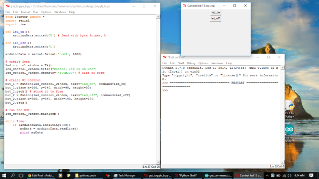
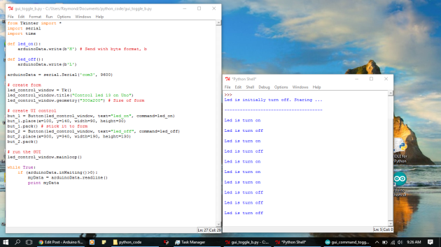
The outcome is not as good as expected. Only when the GUI is closed, Arduino sends back the message. I should not use 2 buttons because there is a chance that I hit turn on when the Led is already turn on.

PA03_gui_totalPA03_gui_without_control

It is a not good result. Maybe I will build a text field to receive the feedback message from Arduino next time. The index of next section will be [PA-03a].


Note: Tkinter with capital "T"

[PA-02] Send data from Arduino via pyserial

Step 1: install pyserial: go to https://pypi.python.org/pypi/pyserial/2.7 download version pyserial-2.7.win32.exe and install to your computer.

Step 2: load the following code to the Arduino, this code will send variable count to the computer via serial port and blink led on pin 13 (1 sec ON, 1 sec OFF to prove that Uno is still working)


/*
 * Arduino and Python Serial Port
 * Date: Thu, 27/04/2017
 * Desc: Serial port testing
 * Arduino counting and sending count via serial port COM3
 * Blink Led 13 to prove alive
 */
int cnt;
void setup() {
 // Initialize variable, procedure and state
 cnt = 0;
 Serial.begin(9600);
 pinMode(13, OUTPUT);
 digitalWrite(13, LOW);
 // Foreword
 Serial.println("Counting demo");
 Serial.println("-------------");
}

void loop() { 
 // and sending count
 Serial.print("I am counting to ");
 Serial.print(cnt);
 Serial.println(" Mississippi.");
 // Counting
 cnt++;
 // Blink Led 13
 digitalWrite(13, HIGH);
 delay(1000);
 digitalWrite(13, LOW);
 delay(1000);
}

Now you can go to: Tools --> Serial Monitor to check the data that Arduino sent to PC.

Step 3: paste the following code in VIDLE VPython


import serial #Import Serial Library

arduinoSerialData = serial.Serial('COM3', 9600)

while(1==1):
 if (arduinoSerialData.inWaiting()>0):
 myData = arduinoSerialData.readline()
 print myData

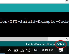
Remember to change to COM port that is suitable in your computer (mine is 'COM3'). You can find your COM port at the bottom-right of your Arduino IDE.  The baud rate will be 9600 at default.

PA02_determine_COM_port

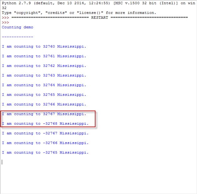
What happens if the variable int cnt reach the maximum positive value (in Arduino code I initiate variable cnt = 32760 in void setup)? Here comes the result:

PA02_integer_max_value

You can press Ctrl+C (corrupt) to terminal the running program. It will help for the next connection without prompting some alarm.

Beware of the variable type and its range and how microcontroller processes variable limit. You do not want to save too much money to bank account and then your account amount will be negative or zero.


That is one-way ticket, from Arduino to PC. Next time, I will show you the other way, from PC to Arduino.

[PA-01] Install Python

Foreword


This serie tutorial will show you how to communicate between Arduino and Python via serial port. Why Arduino? Because Arduino is the most popular till now. Why Python? Python is lightweight and I want to use Python with Raspberry Pi so this is how I met Python.

This serie is based on the work of Mr.Paul McWhorter with my modification. I honor his name because he makes it clear and effective for the newbies. You can visit these URL for reference:

Youtube: https://www.youtube.com/watch?v=95w4sx_zoB8&list=PLGs0VKk2DiYylFUUMMv9WiL3x3tpscDUQ

Website: http://www.toptechboy.com/using-python-with-arduino-lessons/ 


The serie Using Python with Arduino will be numbered with the syntax [PA] hyphen [2 digits of tutorial’s order]. This is [PA-01] tutorial and I will show you how to install Python on Window 10 64-bit

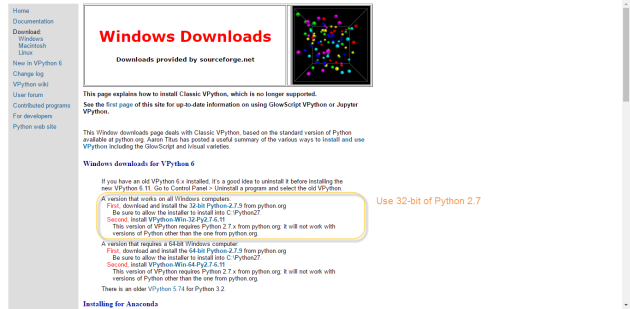
Step 1: go to http://vpython.org/contents/download_windows.html and follow 2 steps

PA01_install_python

Step 2: setup Environment Variables

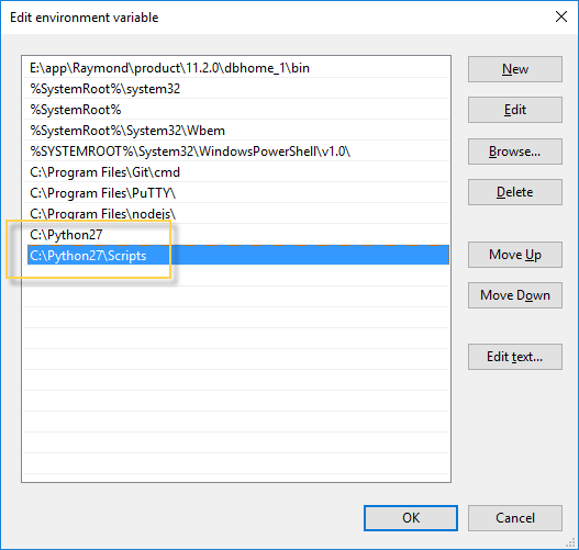
Control Panel\System and Security\System –> Advanced system settings –> Environment Variables –> (below) System Variables –> Path –> (button) Edit –> New (add 2 directory C:\Python27 and C:\Python27\Scripts –> OK –> OK –> OK

PA01_install_setup_env var

Step 3: create folder python_code in Documents, this will save the code. Open VIDLE for VPython and type this code:

[Code]


print "Hail Hydra"

Then save it in the folder python_code with the name hello_world.py (remember the format .py). Run –> Run Module (or press F5) to execute the code in Python Shell and it will print out the phrase. To terminal the code excution press Ctrl+C (corrupt) the code (you do not need to press Ctrl+C right now, it is one step ahead)


Now it is finished. Next tutorial will show you how to install serial library on python with pyserial and how to use it.